


- Yokohama-shi Top Page
- Business
- Menu by field
- Architecture and Urban Planning
- Construction-related procedures, laws and regulations, and approvals
- Ordinances and Regulations on Buildings
- About Yokohama standard wave, Yokohama simulated ground motion
- About characteristics of Yokohama standard wave (yoko face)
The text is from here.
About characteristics of Yokohama standard wave (yoko face)
Last updated on July 29, 2024.
Progress of creation
The Yokohama Standard Wave was created as an input ground motion for the basic fixed model of the building based on Yokohama simulated ground motion (input ground motion time history waveform name: yoko face) as a result of the examination of the "Yokohama High-rise Building Seismic Guidance Standards Development Committee" conducted in 1992.
Notes
This Yokohama standard wave can be used for buildings built in the Yokohama city area, but special shapes (equivalent frame type such as mega frames, ground connection model type etc.)・ In the case of buildings with conditions (large-scale slope buildings), etc., it is necessary to handle them carefully.
How to create Yokohama Standard Waves
![]() Preparation policy
Preparation policy
In order to understand the behavior of buildings during an earthquake, it is necessary to appropriately evaluate the interaction effect between buildings and the ground. Since actual earthquake observation records contain the effect of interaction between buildings and the ground, it is common to be smaller than the observation waveform of the free ground. In addition, according to the analysis results, the speed response spectrum of the first floor position tends to be smaller than that of the free ground surface in the vicinity of the building cycle. Based on these facts, when creating the Yokohama standard wave, the effect of interaction was incorporated and created using the following procedure.
(a) Using the Yokohama simulated ground motion, the joint vibration response analysis of the building and the Yokohama area (MM21, Shin-Yokohama) surface ground is performed using the building cycle as a parameter, and the horizontal ground motion spectrum at the first floor is set.
(b) Create an acceleration waveform that simulates the horizontal seismic motion spectrum of the floor position on the first floor, and this is used as the Yokohama standard wave. When setting the horizontal seismic motion spectrum at the floor position on the first floor, since the height of the building for the seismic response analysis is about 45m to 60m, we will mainly consider the period around 1 to 3 seconds.
![]() Basis of Yokohama simulated seismic motion spectra and time history waveform
Basis of Yokohama simulated seismic motion spectra and time history waveform
The horizontal seismic motion spectrum of the platform of Yokohama simulated seismic motion is defined as the ground motion when the top surface of this platform is regarded as a free surface by using the claytan layer (the shear wave velocity Vs of about 430 m/sec) as the free surface. The simulation ground motion is created by superimposing sine waves, and the waveform of the simulated ground motion has a maximum acceleration and maximum speed value of 350 cm/sec2 and 62.0 cm/sec, respectively, and the duration is 80 seconds.
![]() Object to be considered and how to solve it
Object to be considered and how to solve it
(a) Ground
The ground to be considered is the Minato Mirai 21 district and the Shin-Yokohama district, and the ground composition is undulating in the base clay layer, and the surface layer shallow below the base layer is soft ground with buried soil and alluvial layers. . In setting the analysis model, three models were set in the Minato Mirai 21 area and two models in the Shin-Yokohama area because the layer thickness of the surface is several tens of meters wide.
(b) Buildings
The plane shape of the target building is a square of 40m x 40m, and the number of floors of the building is assumed to be about 10 to 30 floors. The primary cycle of the building examined is 0.5 seconds, 1.O seconds, 1.5 seconds, 2.5 seconds, 3.O seconds, 6 types.
(c) Solving method
The seismic response analysis of the ground and buildings was performed using the equivalent linear method based on one-dimensional wave theory. In the analysis model, the ground and buildings were replaced with a shear-type pending system with a unit cross-sectional area, and a viscosity boundary was established on the upper surface of the base. The rigidity of the building was linear and the attenuation was reduced to 2%. Here, the rigidity distribution of buildings assumes that the rigidity of the top layer is 1/2 of the rigidity of the first floor, and the middle floor is obtained by linear interpolation. The rigidity and attenuation of the ground were nonlinear. The calculation of the speed value of the waveform of the obtained response analysis results was obtained by integrally integrating the acceleration waveform by Trifunac method.
(d) Ground-only response analysis results
Consideration was conducted when the Yokohama simulated ground motion was input to a model only for the ground. The response of the ground is large, and the degree of nonlinearization is also large. The maximum acceleration and speed values of the surface based on the ground-only response are 300 to 400 cm/sec2 and 70 to 90 cm/sec, and are characterized by a larger speed value than the acceleration value.
Furthermore, if we adjust Yokohama mock seismic wave on the base so that the maximum speed of the surface is 25,50 cm/sec, it will be 0.7 times from O.5 at 50 cm/sec and 0.23 to 0.34 times at 25 cm/sec. At that time, the maximum surface acceleration value was 180 to 270 cm/sec2 at 50 cm/sec, and 120 to 180 cm/sec2 at 25 cm/sec.
(e) Response analysis of ground and building interconnection systems
In the ground and building combination vibration analysis model used here, the building and ground are modeled as a continuous unit of cross-sectional area, and weight and rigidity are evaluated. For this reason, when the weight density of the building is simply calculated by dividing the building weight by the volume of the building is used for the ground, the interaction effect is overestimated. Therefore, in this analysis, we examined the case where the weight density of the building is actually increased by 3/4 times and 1/2 times.
![]() Setting Yokohama Standard Waves
Setting Yokohama Standard Waves
(a) Setting the horizontal seismic motion spectrum
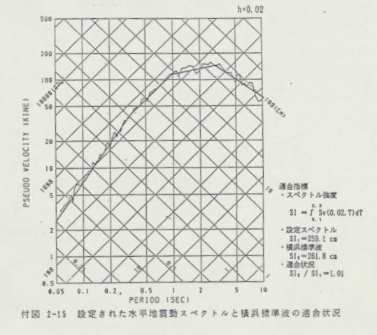
Based on the results of the vibration response analysis of the ground and building interconnection system, the horizontal seismic motion spectrum of the first floor position incorporating the effects of interaction is shown in the form of a pseudo-response spectrum with attenuation of 0.02. The set horizontal seismic motion spectrum is consistent with the response results of the Tokyo coastal area, taking into account the interaction between the ground and buildings in the target periodic area (around 1 to 3 seconds), and is not underestimated in the periodic area outside the target area.
In addition, considering the interaction, this spectrum, which encompasses five types of ground response results in the Yokohama area, can be an effective method from the viewpoint of design practice. The horizontal seismic motion spectrum set here is equivalent to Level 2 earthquake, and Level 1 earthquake is 1/2.
(b) Creation of Yokohama Standard Waves
Create an acceleration waveform that simulates the horizontal seismic motion spectrum of the 1st floor position set, and this is used as the Yokohama standard wave (input seismic motion time history waveform for design: yoko face). The method of creating the Yokohama standard wave is Watabe Todo; "Study on simulated seismic motions for design Part 3D simulated seismic motions for seismic design" was performed by superimposing sine waveforms using HACHlNOHE NS 1968 as a phase characteristic. The continuation time was set to 40 seconds because the target building cycle is about 3 seconds or less.
Spectrum and waveform of Yokohama standard wave
 (Image: 39KB)
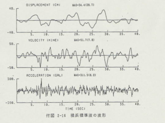 (Image: 23KB)
Inquiries to this page
Housing and Architecture Bureau Building Guidance Department, Building Guidance Division
Phone: 045-671-4536
Phone: 045-671-4536
Fax: 045-681-2437
E-Mail address [email protected]
Page ID: 432-505-245


